
Vertical HF Antennas
A Vertical Antenna is an antenna that stands upright, much like a pole. It is popular among amateur radio operators because it takes up less space than many other antennas and can perform very well for long-distance HF communications, also known as DX.
One of the biggest advantages of a vertical antenna is its omnidirectional coverage. This means it can send and receive signals in all directions around it, so you generally do not need a rotor to turn the antenna toward different stations. Vertical antennas can also have a low takeoff angle, meaning much of their signal travels toward the horizon rather than straight up. This can be beneficial for reaching stations hundreds or even thousands of miles away.
Vertical antennas are ideal when space is limited. They can be installed in a small backyard, mounted on a vehicle, or carried to a park for Parks on the Air (POTA) activities. They are generally simpler to erect than large directional beam antennas, and some models cover multiple HF bands using traps, loading coils, adjustable elements, or matching networks.
One important part of many vertical antenna systems is the radial system. Radials are wires that extend outward from the antenna and help provide a return path for RF current. They can be buried underground or installed above ground, depending on the antenna design. A properly designed radial system can significantly improve efficiency.
Vertical antennas can sometimes pick up more local electrical noise than horizontal antennas, although this depends on the surroundings and installation. Nearby buildings, trees, and metal objects can also affect performance.
Overall, vertical antennas offer a compact, versatile solution for amateur radio operators who want to make long-distance contacts without needing a large amount of space.
Scroll Down to see the various types of Vertical Antennas
POTA PERformer
Rybakov
1/4 Wavelength (1/4λ) Vertical
5/8 Wavelength (5/8λ) Vertical
1/2 Wavelength (1/2λ) Vertical
Linked Multiband Vertical
Coils (Loading Coils)
Trap Multiband Vertical
POTA PERformer
Rybakov Antenna
Rybakov Antenna
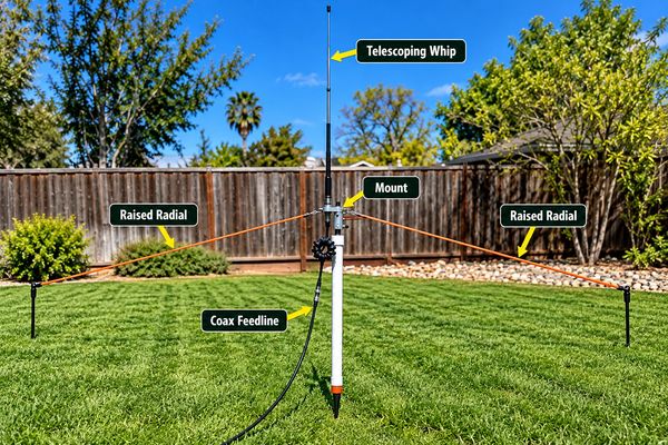
The POTA PERformer (Portable, Elevated, Resonant), designed by Greg Mihran KJ6ER, features an elevated quarter-wave design with two raised radials.
With raised linked radials is a refined portable vertical antenna system designed to improve efficiency and simplify band changes during POTA activations or field operations. Instead of laying radials directly on the ground, the raised radial system elevates them slightly above ground level, which can reduce ground losses and improve radiation efficiency. The “linked” design allows operators to quickly change bands by clipping or unclipping sections of the radial wires, effectively adjusting their electrical length without needing an antenna tuner in some configurations. Paired with a telescoping whip and matching transformer, this setup offers fast deployment, cleaner tuning, and stronger signal performance—making it especially attractive for activators who want reliable multiband operation with minimal setup time in the field.
The POTA PERformer antenna provides a maximum gain of approximately 0.3–0.5 dBi with radials arranged at 90° or 180°.
90° Radials: Provide 3–4 dB (up to 8 dB in some reports) front-to-back ratio for mild directionality.
180° Radials: Provide a more omnidirectional pattern.
Efficiency: The elevated, resonant design ensures >90% efficiency.
Radiation Angle: Features a low radiation angle (approx. 12°–15°) ideal for DX.
Directionality: The 90-degree configuration offers roughly -12 dB or up to 2 S-units of directivity.
Mounting: The elevated, resonant, and tuned nature of the radials reduces near-field ground losses.
You can find the design and how to on several websites:
Rybakov Antenna
Rybakov Antenna
Rybakov Antenna
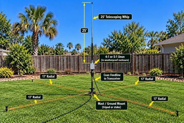
The Rybakov antenna, often called the Rybakov 806, is a popular multiband HF antenna associated with Enrico IV3SBE. It offers amateur radio operators a simple, lightweight, and versatile solution for portable operating, Field Day, and Parks on the Air (POTA). The “806” designation refers to its intended coverage from 80 through 6 meters when used with suitable matching equipment.
The antenna typically uses approximately 7–8 meters (23–26 feet) of wire or a similarly sized telescoping whip connected through an impedance transformer. A 4:1 unun is common, although some operators, including me, use a 5:1 unun. A counterpoise wire or radial system provides a return path for RF current and can influence overall performance.
One of the Rybakov’s biggest advantages is its flexibility. The wire version can be suspended vertically from a portable mast or sloped from a tree, while the telescoping-whip version allows for quick setup without needing to throw a line into a tree. Both configurations are compact, lightweight, and easy to transport.
An important consideration is the antenna tuner. Although the Rybakov can operate across multiple HF bands, the impedance presented to the radio varies with frequency. An external antenna tuner may be needed on some bands to achieve an acceptable match, and certain configurations may exceed a tuner’s matching range. A tuner does not eliminate feedline or antenna losses, so a good counterpoise and suitable installation remain important.
For operators seeking an affordable, adaptable antenna for portable HF operation, the Rybakov 806 offers a practical way to explore multiple bands with a single antenna system.
Quarter-Wavelength (1/4λ) Vertical
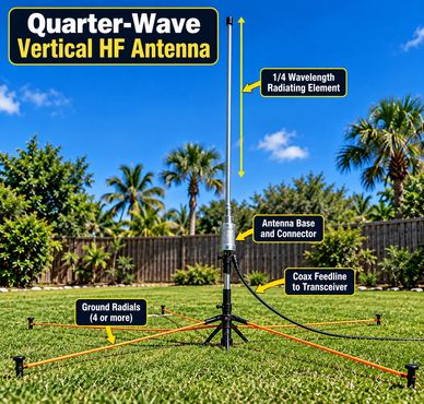
A quarter-wave vertical antenna is one of the simplest and most popular antenna designs in amateur radio. It uses a vertical radiating element approximately one-quarter of a wavelength long, making it relatively easy to build, tune, and install. Quarter-wave verticals are commonly used for HF, VHF, and UHF communications, depending on their dimensions.
One of the biggest advantages of a quarter-wave vertical is its low-angle radiation, which can be excellent for long-distance HF contacts, also known as DX. Its vertical orientation also provides roughly omnidirectional coverage, allowing you to communicate with stations in different directions without turning the antenna.
Because a quarter-wave vertical is typically an unbalanced antenna, it needs an appropriate RF return path. This is often provided by radials—wires extending outward from the antenna base. Radials may be installed on the ground, buried just below the surface, or elevated, depending on the design. A good radial system helps improve efficiency and overall performance.
Quarter-wave verticals can be built from aluminum tubing, a metal whip, or wire supported by a mast. They are useful for home stations, mobile installations, and portable activities such as Parks on the Air (POTA). Their relatively simple construction makes them a great project for new amateur radio operators.
The main limitation is that a quarter-wave element can become physically long on lower HF bands. For example, a quarter-wave radiator for 20 meters is approximately 16.5 feet long, while one for 40 meters is about 33 feet.
When properly installed with a suitable radial system and feedpoint arrangement, a quarter-wave vertical can provide an effective, affordable antenna for reliable HF communications and worldwide DX contacts.
Five-Eighths-Wavelength (5/8λ) Vertical
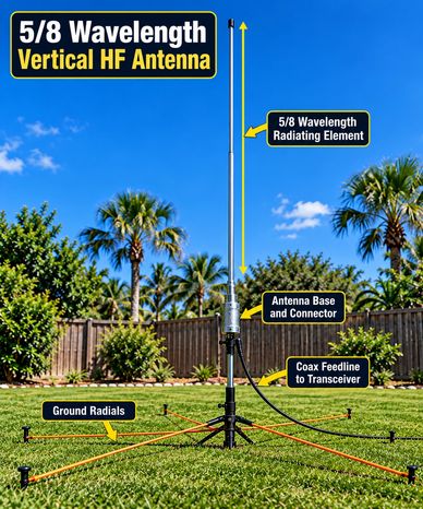
A five-eighths-wavelength (5/8λ) HF vertical antenna uses a radiating element approximately five-eighths of a wavelength long at its operating frequency. Unlike a standard quarter-wave vertical, the longer element can produce a favorable low-angle radiation pattern when properly designed and matched, making it useful for long-distance HF contacts, also known as DX.
One advantage of a 5/8λ vertical is its potential to concentrate more signal toward the horizon than a quarter-wave vertical under suitable installation conditions. This can help operators reach distant stations, particularly when the antenna has an effective ground or radial system. Like other vertical antennas, it generally provides omnidirectional coverage in the horizontal plane, so no rotor is needed to change direction.
The main challenge is its physical size. On 20 meters, a 5/8-wavelength element is approximately 41 feet long; on 40 meters, it is about 82 feet. For this reason, full-size 5/8λ HF verticals are often impractical for smaller properties. Some designs use loading coils or other electrical techniques to shorten the antenna, although shortening generally introduces efficiency and bandwidth trade-offs.
A suitable matching network is usually needed because a 5/8λ element does not naturally present a convenient 50-ohm feedpoint impedance. A good radial system is also important for providing an RF return path and improving performance.
For HF operators with sufficient space, a properly designed 5/8λ vertical can be an interesting option for DX operating. However, its actual advantage over a quarter-wave vertical depends on the design, ground system, installation, and operating frequency.
Half-Wavelength (1/2λ) Vertical
Half-Wavelength (1/2λ) Vertical
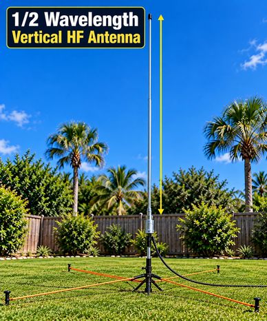
A half-wavelength (1/2λ) vertical antenna uses a radiating element approximately half the wavelength long at its operating frequency. It is a popular antenna design for HF operators seeking effective performance for both regional communications and long-distance DX contacts. (As a note, at this required length, I would gravitate to a EFHW Antenna w/ a 49:1 unun)
One advantage of a half-wave vertical is that it can be designed to operate without the extensive ground-radial system typically needed by a quarter-wave vertical. Many half-wave designs use a matching network at the base to transform the antenna’s feedpoint impedance to a value suitable for a 50-ohm coaxial feedline. However, the exact requirements depend on the antenna design, and some configurations still benefit from radials or counterpoise wires.
Like other vertical antennas, a half-wave vertical generally provides omnidirectional coverage around the horizon. Depending on its height, surroundings, and design, it can produce useful low-angle radiation for reaching distant stations. This makes it attractive for operators who want DX capability without installing a large directional beam antenna.
The main drawback is its physical length. A half-wave vertical for 20 meters is approximately 33 feet long, while one for 40 meters is about 66 feet. Shorter versions are available using loading coils or other techniques, but these can reduce efficiency and bandwidth.
Some half-wave verticals are designed for a single band, while others use traps, matching networks, or other arrangements to cover multiple HF bands.
For operators with sufficient mounting height, a properly designed half-wave vertical can provide excellent HF performance. Its potential to operate without a large radial field makes it particularly appealing where ground space is limited.
Linked Multiband Vertical
Half-Wavelength (1/2λ) Vertical
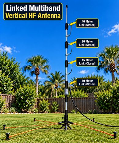
A linked vertical antenna is a versatile HF antenna that allows amateur radio operators to change bands by connecting or disconnecting sections of the antenna element. Instead of using traps or a complex matching system, it uses removable electrical connections, called links, to change the active length of the antenna.
For example, a linked vertical designed for 40, 20, 15, and 10 meters can use different combinations of wire or telescoping sections to achieve resonance on each band. To change bands, the operator opens or closes the appropriate links, adjusting the antenna's electrical length for the desired frequency.
One of the biggest advantages of a linked vertical is its simplicity. It can be lightweight, inexpensive, and easy to transport, making it an excellent option for Parks on the Air (POTA), portable field operations, and emergency communications. Because the antenna is adjusted for each band, it can operate without an antenna tuner when properly designed and tuned, although a tuner may still be useful for small adjustments.
Like other vertical antennas, a linked vertical generally provides omnidirectional coverage and can offer useful low-angle radiation for long-distance DX contacts. A suitable radial or counterpoise system is important for many designs to provide an RF return path and improve efficiency.
The main drawback is that changing bands requires physically adjusting the links, which can take more time than simply switching bands on a radio. However, this straightforward design avoids the added complexity of traps and can provide good performance when properly installed.
For operators who value simplicity, portability, and efficient operation across multiple HF bands, a linked vertical antenna is a practical choice for both home and field use.
Coils
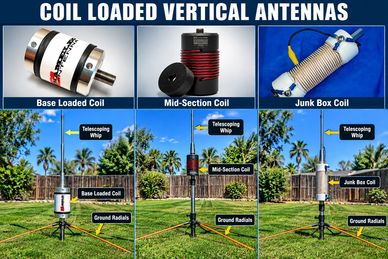
A coil-loaded vertical antenna is designed to provide multiband HF operation while taking up less space than a full-size antenna. It uses a loading coil to add inductance, electrically lengthening a physically shorter antenna so it can resonate on lower frequencies.
The loading coil is typically installed near the base or along the antenna’s middle section. By adjusting the coil or changing its configuration, operators can tune the antenna for different bands. Coil-loaded verticals are popular for mobile installations, small backyards, and portable activities such as Parks on the Air (POTA), where carrying or erecting a full-size quarter-wave antenna may not be practical.
One advantage of these antennas is their compact size and portability. Many designs can operate on several HF bands using interchangeable coils, adjustable whips, or built-in matching systems. Their vertical orientation can also provide useful low-angle radiation for long-distance DX contacts.
However, shortening an antenna comes with trade-offs. Loading coils introduce some losses, and shorter antennas generally have narrower bandwidth than full-size verticals. This means more frequent tuning may be necessary when changing frequencies. A good ground or radial system is also important for many vertical designs because it provides a return path for RF current and can improve efficiency.
Despite these limitations, a well-designed and properly tuned coil-loaded vertical can be an effective solution for operators who want HF performance in a compact package. For portable operators and mobile stations, it offers a practical balance between size, convenience, and the ability to make contacts across multiple amateur radio bands.
Trapped Multiband Vertical
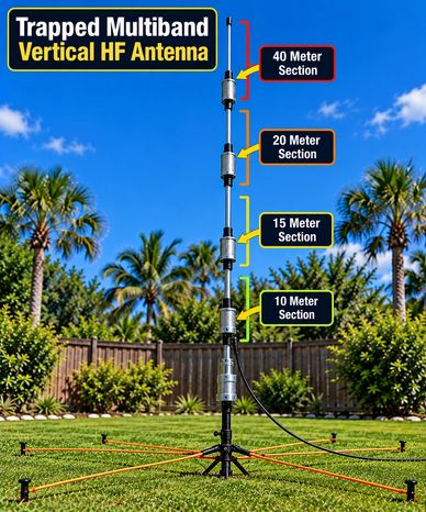
A trapped multiband vertical antenna allows amateur radio operators to work several HF bands using a single vertical antenna. It uses special components called traps, which are electrical circuits containing inductors and capacitors. Each trap is designed to affect the antenna's operation at a particular frequency, allowing different sections of the antenna to function on different bands.
For example, a trapped vertical designed for 10, 15, 20, and 40 meters can use traps to electrically isolate portions of the antenna at selected frequencies. This makes it possible to operate on multiple bands without installing a separate antenna for each one.
One of the biggest advantages of a trapped vertical is its compact footprint. It takes up relatively little yard space, provides generally omnidirectional coverage, and can offer useful low-angle radiation for long-distance DX contacts. This makes it attractive for home stations where space is limited.
Most trapped verticals use a ground system consisting of radials or another suitable RF return arrangement. The quality of this system can significantly affect antenna efficiency and performance. Proper installation and tuning are also important to achieve acceptable SWR across the desired bands.
Traps add convenience, but they can introduce some electrical losses and may limit bandwidth compared with a simpler full-size antenna. Performance depends on the antenna design, trap quality, mounting height, and surrounding environment.
For operators who want to cover multiple HF bands with one relatively compact antenna, a trapped multiband vertical offers a practical balance of convenience, space savings, and DX capability.